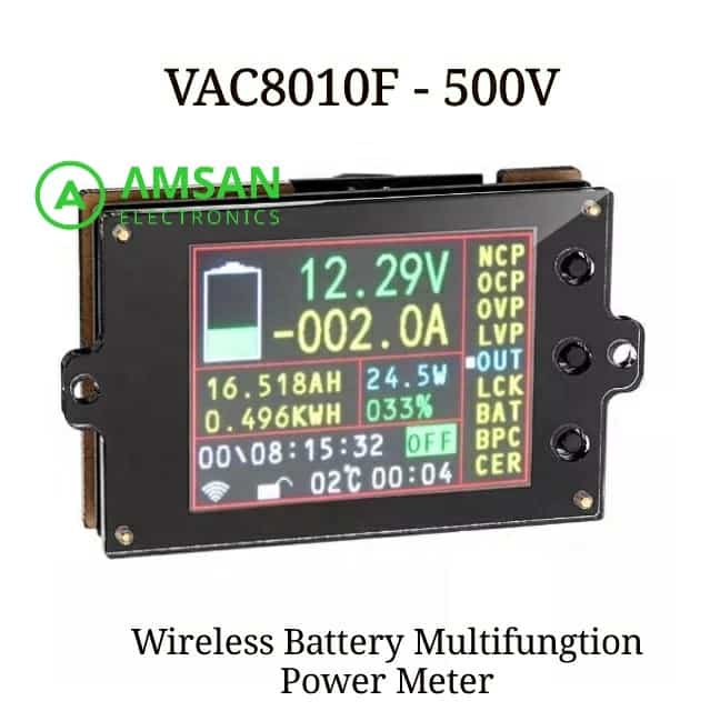
Deskripsi
The instrument through the charging and discharging relay interface with its own relay can be achieved automatically switch charge and discharge, you can also manually switch by pressing the button charge and discharge.

The instrument has a total of 18 functions, each function to help customers more convenient and faster access to more accurate measurement results.
(1) NCP: set the value of charge over-current protection, with the relay can be achieved when charging over-current protection;
(2) OCP: set the discharge over-current protection value, with the relay can be achieved when the discharge over-current protection;
(3) OVP: Set the charge overvoltage protection value (the voltage exceeds the set voltage can automatically fill the capacity), with the relay can be filled with automatic disconnection function;
(4) LVP: set the discharge over-voltage protection value, with the relay can be achieved automatically disconnect the discharge function;
(5) OUT: The switch output function of the wireless control relay can be realized by clicking OUT.
(6) LCK: key lock function, if necessary, you can lock the keys to prevent misoperation;
(7) BAT: the default total battery capacity; reference value as a percentage of capacity;
(8) BPC: preset remaining battery capacity percentage and remaining battery capacity;
(9) CER: current return to 0 function, when the no-load current is not 0, you can click this option to clear the current;
(10) RET: WH and run-time value reset function, to facilitate the next measurement;
(11) LNG: language switching function, the instrument has built-in Chinese and English languages, you can switch languages through this option;
(12) STI: set the relay power-on default state, open or closed;
(13) SFH: device search function, through this feature can be one-to-many communication;
(14) DEL: set the relay delay working time; to achieve the protection of the relay delay action
(15) FCH: communication address modification function, if multiple groups of modules at the same time each group of modules to set a different address to prevent interference;
(16) SNR: set the screen current, when the SNR is greater than 0, and the screen time value is not 0, you can achieve automatic screen function, and when the charging current is less than this value, the cumulative charging capacity is not to avoid floating charge The impact of the capacity value, when the current is greater than this value LCD screen automatically lit.
(17) SNT: Set the screen time value. When the SNT value is 0, the LCD panel never goes out. When the SNT value is greater than 0 and the SNR is also greater than 0, the automatic screen and bright screen functions can be realized.
(18) RFS: display color switch function, this instrument has two color matching customers can choose different color according to their preferences.
have the Temperature measurement function
The main features
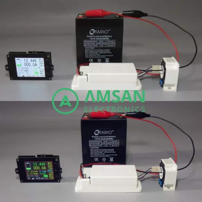
1, wireless transmission of data, to avoid the complex wiring between the display and detection modules to bring interference, while wiring is more simple.
2. Hall sensor is used to realize non-contact detection current without disconnecting wires, which is safe, reliable and convenient.
3, voltage, current, power, temperature, capacity, percentage of remaining capacity, running time is displayed at the same time.
4, double relay interface, you can manage charge and discharge separately.
5, with charge over voltage, discharge under voltage, charge over-current, discharge over-current protection.
6. The memory function of the breakpoint, power-on and power-off, and the number of AH and WH before power-off can be memorized.
Project parameters
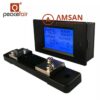
Display:2.4 inch TFT LCD display
Self-power measurement range of 6V ~ 80V
Measurement range 0~500V when external power supply
Input current measurement range 0~100A
External supply voltage 6-60V
Display mode 2.4 inch color LCD display
Voltage 0.01V~500V
Current 50A 100A 200A 300A 500A can choose
Notice:If you want measuring less than 1A current ,pls choose the 50A Meter
Capacity 0.001AH~65000.00AH
Energy 0.000KWH~9999KWH
Time 0 ~ 100 hours
Power value 999KW
Temperature 1~100°C
Voltage ± 1% + 2 words
Current ± 2% + 5 words
Temperature ± 1.5 ℃
Measurement rate 5 times / second
Relay delay time (0-60)S
Communication distance Open single group 10 meters
OVP (overvoltage protection) 0.01V~500V
LVP (undervoltage protection) 0.01~500V
OCP (Charge Overcurrent Protection) 0-500A
NCP (discharge overcurrent protection) 0-500A
Display board size 87 * 49 * 14 (mm)
Measuring plate size 114 * 54 * 28 (mm)
common problem
1; accuracy problem? Resolution?
The accuracy of the meter current is ±1%+5 characters of the measured current value; for example, when measuring 10A current, the limit error is ±0A to 0.6A, which is generally very accurate in practice; of course, the measured current value of the meter is basically close to the measured value; The resolution of 50A is 0.01A; the resolution of 100A is 0.1A; the resolution is the display value;
2; settings
If there is no relay installed, generally only need to set the battery BAT; the remaining battery percentage BPC; the charging voltage reaches the set value and automatically fill the battery OVP; the no-load current clears the CER; the screen color switch RES; do not operate other options at will, please be familiar Documentation
3; Pay attention to the wireless module behind the wireless meter display screen, do not short-circuit or loosen it; do not operate the channels SFH, FCH at will; the display screen and the measuring box cannot be too far or blocked too much, which will affect the signal transmission; this will affect the data transmission In place, the parameters all display 00;
4; The values of SFH and FCH are the same; if there is no other problem, the channel offset causes the data to display 00; you need to search for the SFH value and make sure that the display voltage SFH value is set to FCH; the correct SFH value, when FCH is set, no matter what Adjust FCH value XX, red 000000 will always display 0000XX;
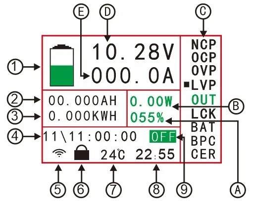
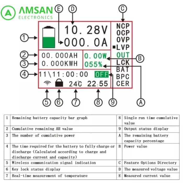
1 Remaining battery capacity Column 8 Accumulated value of single run time
2 Accumulated remaining AH number 9 Output status display directory
3 Accumulated Energy
4 The time it takes to fully charge or discharge the battery (calculated based on charge and discharge current and capacity)
5 wireless communication signal indicator
6 Key lock indication
7 Real-time measurement of temperature
A Percentage of Battery Remaining Capacity
B Power value
C function options directory
D Actual voltage value
E Actual measured current
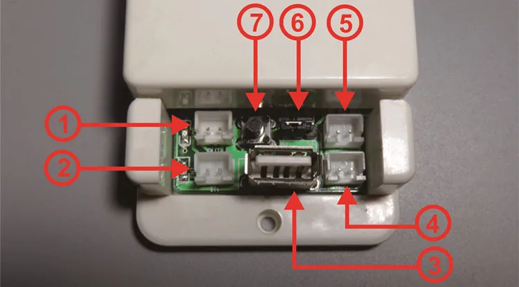
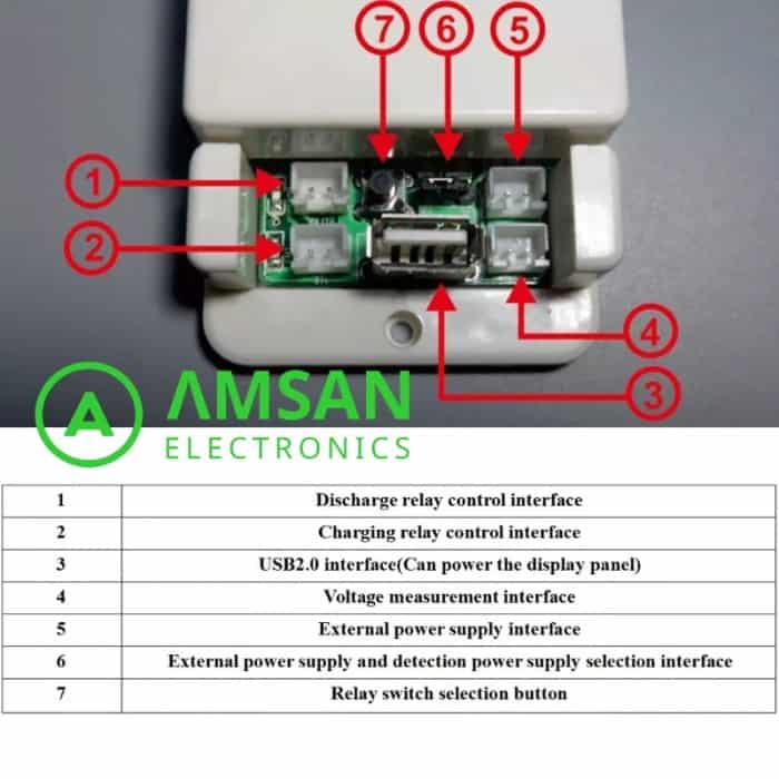
1 discharge relay control interface
2 charging relay control interface
3 USB2.0 interface (for display panel power supply)
4 Voltage Measurement Interface
5 External power supply interface
6 external power supply and its own choice of power interface
7 relay switch button
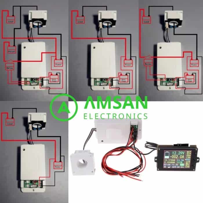
Wiring
Note: If the measured battery (power) voltage (6-80) V range can be battery (power) its own power supply wiring, if the measured battery voltage is greater than 80V or less than 6V should be used for external power supply wiring; voltage if not (6-80) V range, please do not use their own power supply wiring, this may damage the measuring instrument.
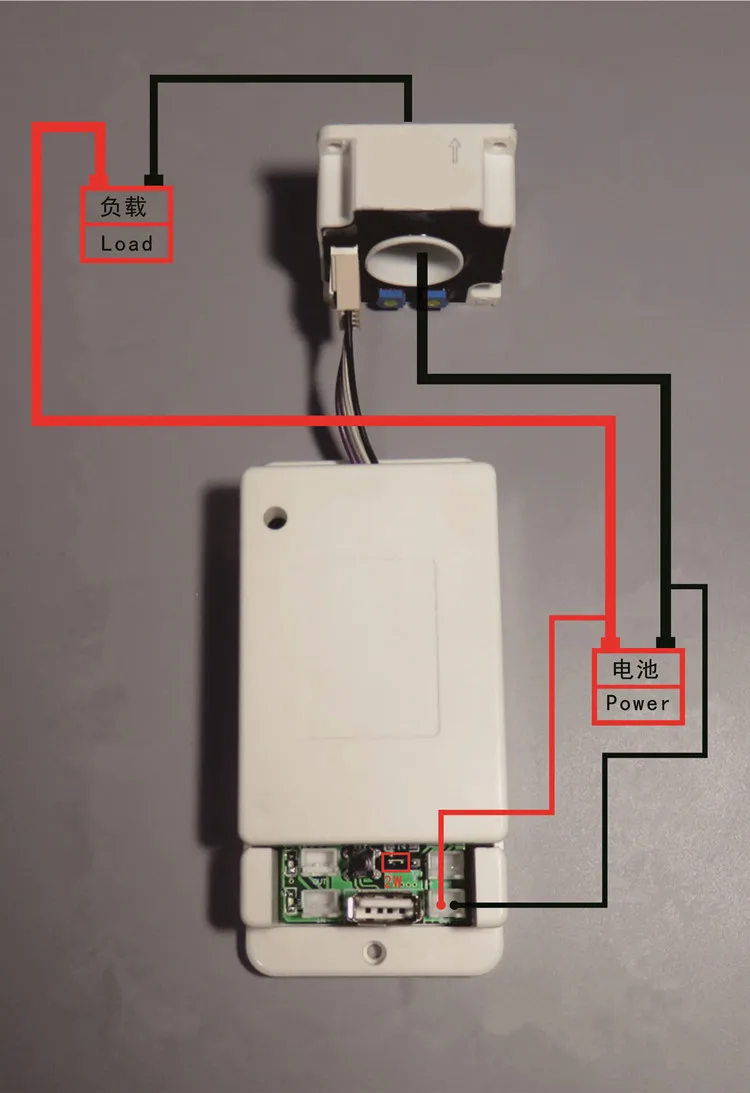
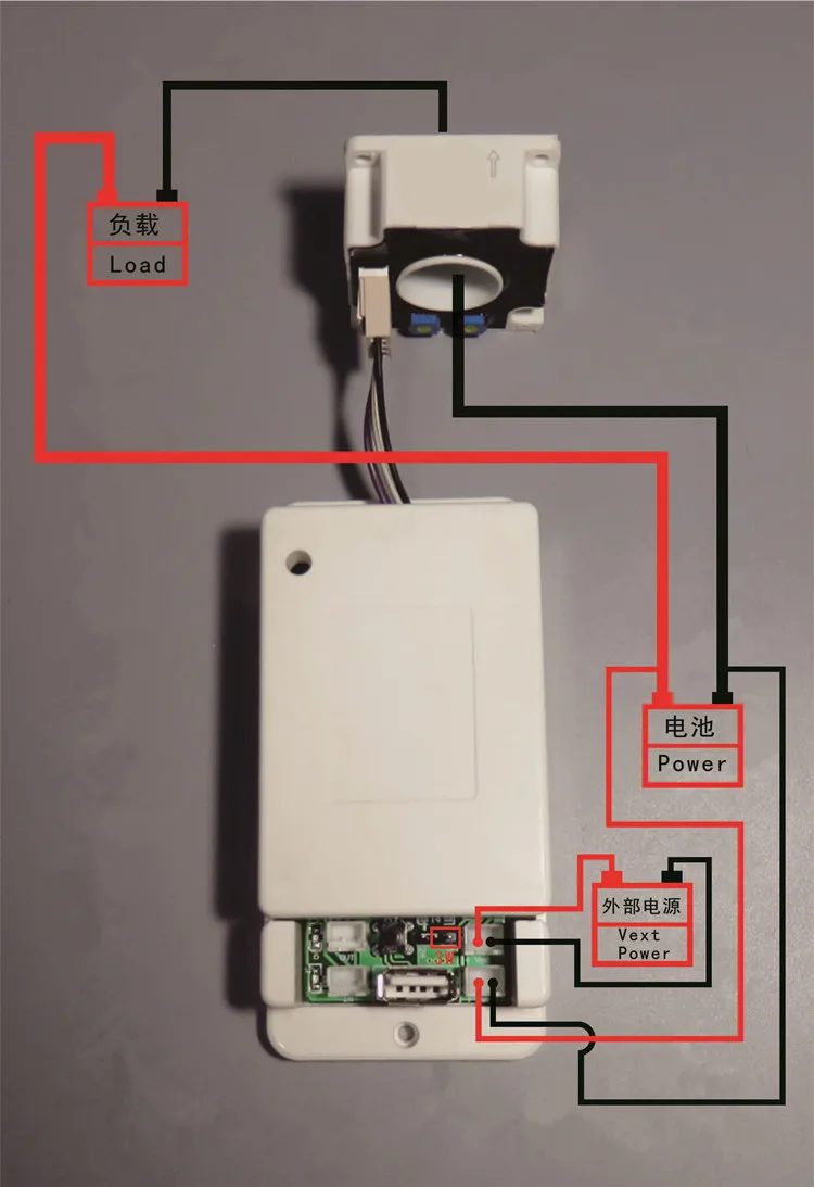
(1) its own power supply wiring diagram
NOTE: If the tested battery (power supply) can work with its own power supply voltage (6-80V) during normal operation, first adjust the jumper cap of the power supply selection interface to “2W”, and then connect The positive and negative poles of the battery (power supply) are connected to the voltage measurement port “+Bat-“; note that “+” connects to the positive terminal of the battery (power supply), and “-” connects to the negative terminal of the battery (power supply). The positive and negative poles of the power supply must not be connected. Wrong or reverse, the battery (power) is connected to the positive pole of the load, the negative pole of the battery (power) is connected to the negative pole of the load through the Hall sensor. When the current flowing through the Hall sensor and the Hall sensor power-on arrow When the direction is the same, the measured current will show a positive value, otherwise the measured current will show a negative value.
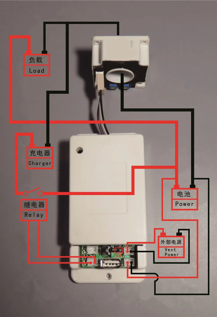
(2) External power supply wiring diagram
Note: If the voltage range of the tested battery (power supply) is not within the range of (6-80V) during normal operation, the external power supply connection mode can be used. First, adjust the jumper cap of the power supply selection interface to “3W” to connect the external power supply. Positive and negative poles are connected to “+Vext-“. Note that “+” is connected to the positive pole of the external power supply, and “-” is connected to the negative pole of the external power source; then connect the positive and negative poles of the battery (power supply) to the voltage measurement port “+Bat – “Department, pay attention to” + “connected to the battery (power) positive,” – “battery (power) negative. The positive and negative poles of the battery (power supply) should not be connected wrongly or reversed. Connect the positive pole of the battery (power supply) to the positive pole of the load. The negative pole of the battery (power supply) is connected to the negative pole of the load through the hall sensor when passing through the hall sensor. Of the current direction and the direction of the Hall sensor power-up arrow when the measured current will be displayed as positive, while the measured current is displayed as a negative value.
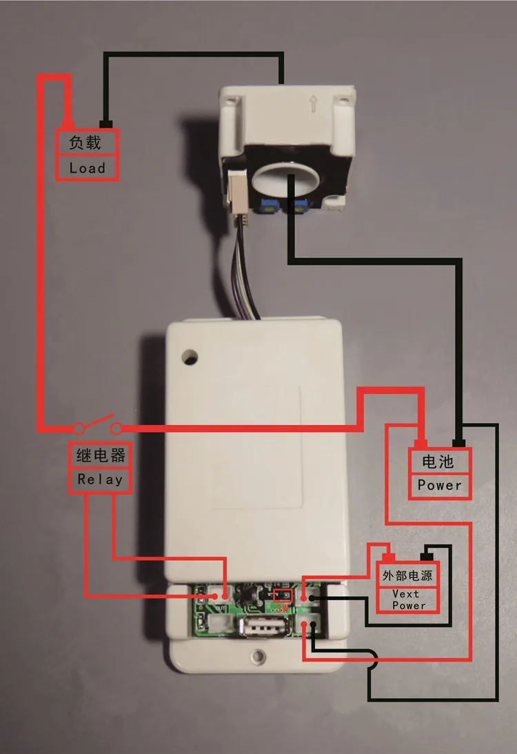
(3) discharge relay wiring diagram
Note: The relay’s working power is provided by an external power supply. If it is connected to a relay, it must provide an external power supply with the same working voltage as the relay. Connect the control port of the relay to the interface of the discharge controller. If you want to control the positive side of the discharge, pass the positive line through the relay. If you want to control the negative side of the discharge, connect the negative line to the relay. When the relay is on, the OUT lamp It will light, off when off as a reminder.
(4) charging relay wiring diagram
Note: The relay’s working power is provided by an external power supply. If it is connected to a relay, it must provide an external power supply with the same working voltage as the relay. Connect the control port of the relay to the interface of the charging controller. If you want to control the positive side of charging, pass the positive line through the relay. If you want to control the negative side of charging, connect the negative line to the relay. When the relay is on, “IN” light It will light, off when off as a reminder
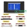
Package include:
1pcs Display Module
3pcs 2P cable
1pcs Male to Male usb 2.0 cable
1pcs tester Module(Include1pcs test board 1pcs Hall Sensor )


Ulasan
There are no reviews yet